![]()
The Tunnel appliance is responsible for handling all the replication management and data traffic making it a critical part of the VMware Cloud Director Availability architecture. From VMware Cloud Director Availability 4.6 on, a second Tunnel can be deployed, and the two operate in an Active/Active mode. This might also positively impact the performance of the appliances as the traffic will be balanced between them.
This new setup is only available for VMware Cloud Director clouds and requires an external load balancer to distribute traffic between the two Tunnel appliances.
In this blog post, we will review the configuration flow and will provide some configuration examples.
- The Tunnel High Availability is only available for VMware Cloud Director clouds and not for dedicated vSphere clouds.
- The Tunnel High Availability configuration can only be applied to the cloud site and NOT to the on-premises site.
- TLS termination and TLS inspection are not supported and, if present, will result in service failure.
- All designs and load balancer configuration examples refer to VMware NSX Advanced Load Balancer. However, it is not mandatory to use it, and any other load balancer that can support TCP balancing can be chosen instead.
- Due to the high volume of replication traffic, it is highly recommended to use a dedicated VMware NSX Advanced Load Balancer Service Engine Group for load balancing the VMware Cloud Director Availability Tunnels.
- To correctly scale the Service Engines, please refer to the VMware NSX Advanced Load Balancer Sizing Compute and Storage Resources.
- The Public Service Endpoint address should be reachable and properly resolvable from the internal network for the other appliances to operate as well as externally for the tenant access.

Both VMware NSX Advanced Load Balancer NSX and vSphere clouds are supported to support the VMware Cloud Director Availability Tunnel high availability.
NSX Advanced Load Balancer with NSX Cloud
This example topology is based on VMware Cloud Foundation implemented according to its design guide.
As stated in the Considerations section, it proposes VMware NSX Advanced Load Balancer with NSX cloud as the load balancing solution.
Due to the fact some of the components are irrelevant to the purpose of this blog post, they are not included in the diagram. You can find the complete information about VMware Cloud Foundation in the documentation.
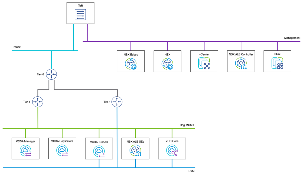
This example topology makes some suggestions, but they are not mandatory:
- Use the same NSX Advanced Load Balancer Controller to load balance the VMware Cloud Director Availability Tunnel appliances and VMware Cloud Director cells
- Utilize the same DMZ network for the public endpoints of both VMware Cloud Director Availability and VMware Cloud Director
- Even though the VMware Cloud Director Availability Tunnels are connected to both DMZ and Reg-MGMT networks, they can remain connected to only one of them if:
- As part of the DMZ network, they can bi-directionally communicate on all needed ports with the rest of the VMware Cloud Director Availability appliances <>
- It is acceptable not to separate internet and local traffic
NSX Advanced Load Balancer with vSphere Cloud
This example topology shows the configuration when a vSphere cloud is used in the NSX Advanced Load Balancer.
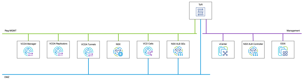
All the suggestions from the NSX Advanced Load Balancer with NSX Cloud section are valid for this example too.
Several steps need to be completed at the cloud site to enable the high availability of the Tunnel appliance.
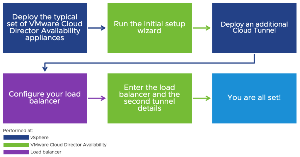
The steps to deploy VMware Cloud Director Availability and run the initial setup wizard are available in the product documentation. Since they remain unchanged, this blog post will not cover them. It will only review the following:
- Load balancer configuration with a VMware NSX Advanced Load Balancer example
- All the additional configurations in the VMware Cloud Director Availability UI to add the second Tunnel appliance and enable the high availability
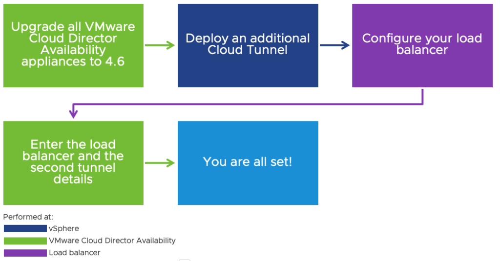
This flow is valid for new VMware Cloud Director Availability installations (greenfield). For environments that run older versions of VMware Cloud Director Availability (brownfield), they first need to be upgraded to 4.6 instead of installing all the appliances from scratch and running the initial setup wizard.
Assuming that the VMware NSX Advanced Load Balancer is already deployed and the dedicated Service Engine Group is created, the following needs to be configured:
- Application Profile
- Health Monitor
- Pool
- Virtual IP (VIP)
- Virtual Service (VS)
Application Profile
The application profiles determine the behavior of virtual services based on the application type.
It is recommended that you can use the System-L4-Application profile, but you can create your own with the same settings if you prefer.
Health Monitor
Active health monitors check the availability of the service for a defined pool of servers by proactively sending queries to them and interpreting the response they receive.
You need to create a TCP monitor that checks the VMware Cloud Director Availability Tunnel state.
To create one, you need to:
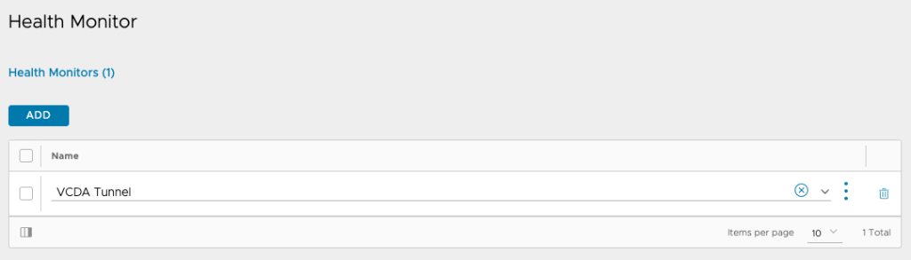
- Navigate to Templates > Profiles > Health Monitors and click on Create.
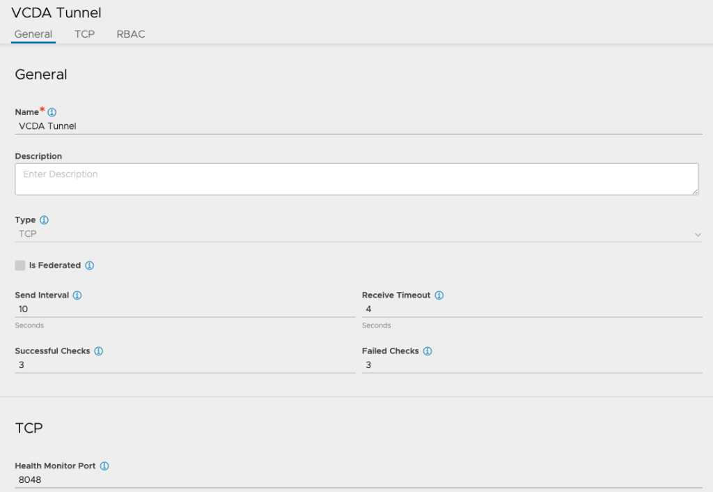
- Provide a meaningful name and select the type to be TCP.
- Under General, set the following values to the settings:
| Setting | Value |
| Send Interval | 10 seconds |
| Receive Timeout | 4 seconds |
| Successful Checks | 3 |
| Failed Checks | 3 |
- Under TCP, put 8048 as the Health Monitor Port.
- Save the health monitor.
Pool
A pool contains the list of servers that will be load balanced. In it, you can configure which health monitor to be used, the persistence settings, timeouts, and more.
To add a new Pool, you need to:
- Navigate to Application > Pools and click on Create Pool.
- Give the pool a meaningful name, and under General, set the Default Server Port to 8048 and the Load Balance Algorithm to Round Robin.

- Set the following values for the Connection settings:
| Setting | Value |
| Connection Ramp | 10 seconds |
| Connections Per Server | 15000 |
| Connection Used Times | 0 |
| Cache Connections Per Server | 0 |
| Default Server Timeout | 60000 Milliseconds |
| Idle Timeout | 60000 Milliseconds |
| Life Timeout | 600000 Milliseconds |

- Add the two Tunnels with their correct IP addresses.
- Add the health monitor that was previously created, and uncheck Enable Passive Health Monitor because of the selected Load Balance Algorithm.
- Under SSL, leave Enable TLS SNI checked.
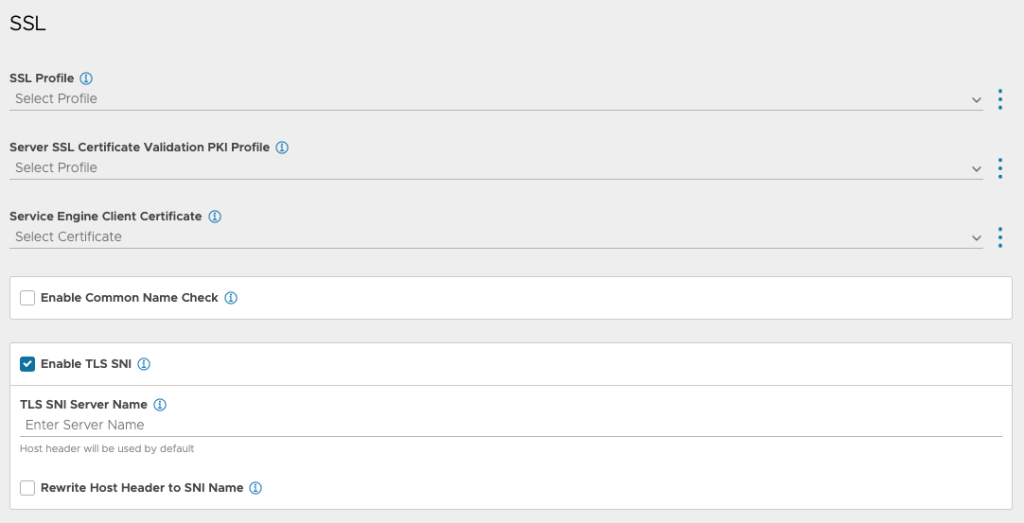
- Save the pool.
Virtual IP (VIP)
Add a Virtual IP that all the VMware Cloud Director Availability appliances can access.
Virtual Service
A virtual service advertises an IP address and ports to the external world and listens for client traffic.
To create a new virtual service, you need to:
- Navigate to Applications > Virtual Services and click Create virtual service > Advanced Setup.
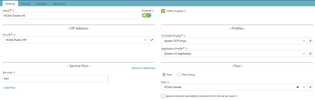
- In Step 1: Settings, give the virtual service a name.
- Select the VIP you added in the previous section as VS VIP.
- Enter 443 as a Service Port.
- Select L4-System-Application as the Application Profile.
- Select the pool you created previously under Pool.
- Proceed to Step 4: Advanced and select the correct Service Engine Group.
- Save the virtual service.
Analytics Profile
It’s common for some applications, including VMware Cloud Director Availability, to send TCP RST (TCP Reset) to close a connection. Because of that, several Connection closed abnormally records will appear in the Virtual Service logs. These can be safely ignored.
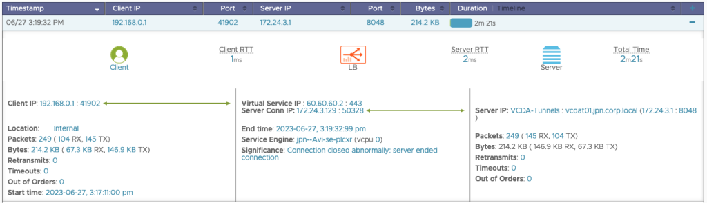
If you would like them not to appear in the logs, you can check Server Connection RST under Network > Exclude Network Errors for the Analytics Profile that you use for the Virtual Service.

After configuring the load balancer, to enable the second Tunnel appliance, there are some steps to perform in the VMware Cloud Director Availability UI:
- Navigate to Settings > Tunnel Settings > Tunnel HA and click on Setup.
- Enter the following:
| Setting | Value |
| TCP Balancer Name | the VIP that the Virtual Service uses |
| Port | 443 (or any other that you have configured the Virtual Service to use) |
| Tunnel Service Endpoint address | the IP address of the second Tunnel appliance |
| Password | the password of the appliance. If you haven’t logged in to it yet, it is the initial password set during the OVA deployment. The wizard will prompt you to change it. |
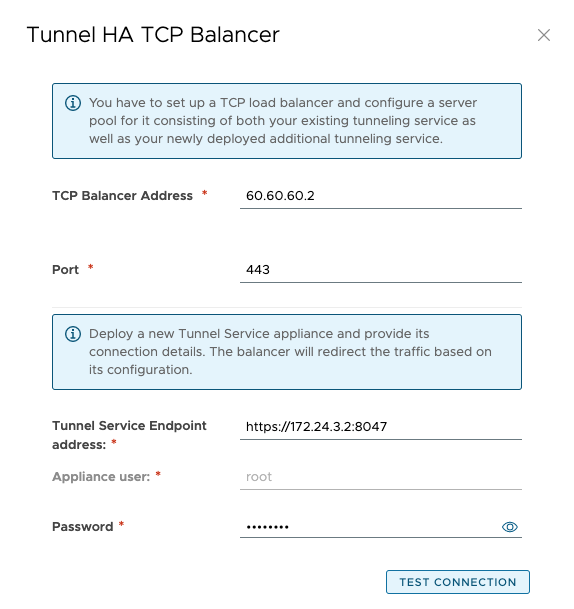
- Click on Test Connection and accept the thumbprints.
- Click OK.
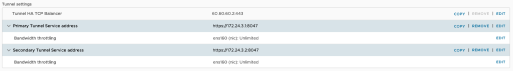
- Under Service Endpoints, make sure the Public Service Endpoint address is correctly set to the public address and port of the VMware Cloud Director Availability instance.

- The configuration is completed.
Setting up high availability for the VMware Cloud Director Availability Tunnel appliances is quite a simple and straightforward process. A second Tunnel needs to be deployed, and an external load balancer needs to be configured.
This setup is supported for new environments as well as for upgraded ones.
Remember, to get the latest updates, check this blog regularly, you also can find us on Slack, Facebook, Twitter, LinkedIn as well as many demo videos and enablement YouTube, especially our Feature Fridays series!